
Draw a rectangle
- Hits: 7014
Learn how to use the rectangle command and the options it provides.
Principle
- Start the command.
- Options.
- Select starting point.
- Options after selecting a starting point.
- End point selection.
Launch the "Rectangle" command
- The first method is to click on the rectangle icon
 (depending on the interface it may look different).
 - The second is to write REC, confirm by pressing the key ß or e - recommended method.
- The third is to repeat the previous command if it was a "rectangle" by pressing the key ß or e.
Options
As soon as you run the rectangle command, the following options appear: Chamfer, Elevatin, Fillet, Thickness, Width.

Chamfer
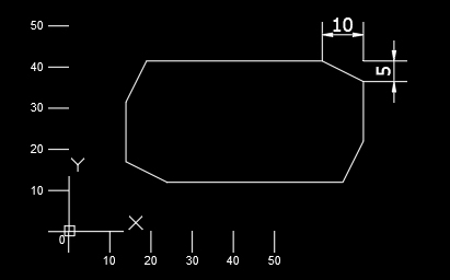
This option will chamfer each corner of the rectangle. Activation is done by pressing the key C and after this e. Then you need to enter two values that will determine the size of the chamfer. If you enter two different values for example first 5 then 10. Първата стойност ще е разстоянието от ъгъла по правата която е по посока на часовника, а втората ще е разстоянието от ъгъла по правата която е по посока обратна на часовника. Това важи за всички ъгли.
Elevation
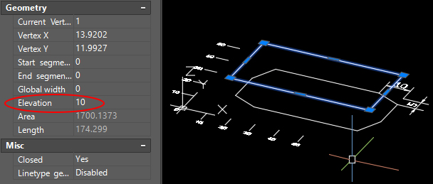
By default, AutoCad creates a rectangle with a value of Z=0. Using the "Elevation" option you can change the Z value. Activation is done by pressing the E key and then e. Then you have to enter the new value for Z and again e.
Fillet
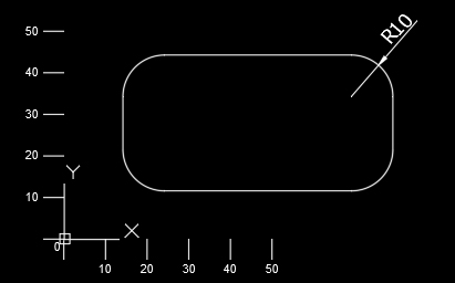
Fillet will round each corner of the rectangle. Activation is done by pressing the key F and after this e. Then you need to enter a value that will determine the radius of the rounding. Confirm the entered value with e.
Thickness
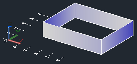
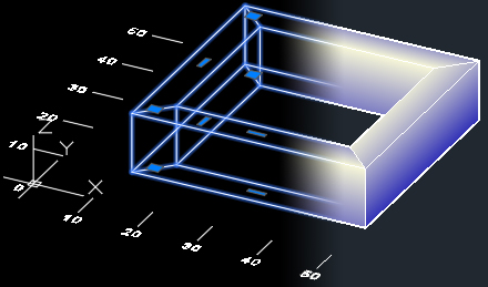
Thickness will outline the rectangle in height, but will not close it to a parallelepiped. Activation is done by pressing the key T and after this e. Then you need to enter a value that will determine the height of the contour. Confirm the entered value with e.
Width
Width will make the contour lines of the rectangle visually wider. Activation is done by pressing the key W and after this e. Then you need to enter a value that will determine the width of the contour line. Confirm the entered value with e. The lines will become as wide as you entered, in the example below the value entered is 5.
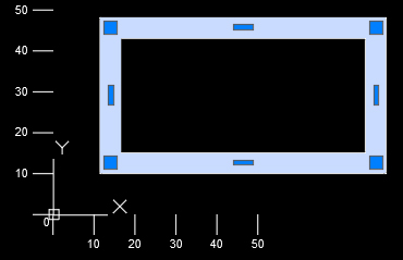
You can apply a combination of Thickness and Width. The figure you will receive will not be a 3-dimensional object. This will remain a polyline, it will just look wide and tall.
Choice of starting point
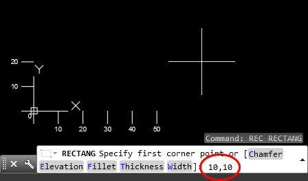
- Option where "dynamic input" ≠ is disabled.
Enter two numbers separated by a comma "10,10". These are the horizontal coordinates "X" and the vertical "Y". Confirm the entered values with e.
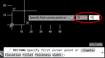
- Option where "dynamic input" ≠ is on.
Enter a number for the horizontal coordinate "X". Press the t button to move to the next field. Enter a number for the vertical coordinate "Y". Confirm the entered values with e.
- Option in which "Snap" £ is on.
A green symbol appears when approaching an attachment point. If you left-click , the beginning of the rectangle will be where the green marker appeared. Although the cursor is not on the point.
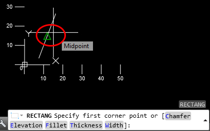
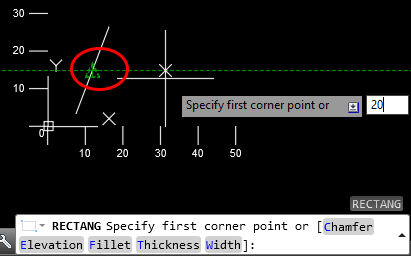
- If you hover over the green symbol, it is marked with a small green plus. You can then move the cursor until a dotted line is displayed. And enter a value such as "20". This will make the beginning of the rectangle 20 of the indicated point in the direction of the dotted line and the cursor. Confirm the entered values with e.
Options after selecting a starting point
After selecting a starting point, AutoCAD will again offer you several options to choose from: Area, Dimentions, Rotation

Area
This option allows you to create a rectangle based on its area depending on one of its sides.
You start the option with A and after this ß or e, enter a value for the area and confirm with e.

Now you need to choose one of the following options: Length или Width.
If you select "Length" with L key, you will need to enter the side length in "X". If you select "Width" with W key, you will enter the side length in "Y". Confirm your choice with e.
Enter the desired length and confirm with e. AutoCAD will calculate the size of the other side of the rectangle and create it to the right and top of the original point.
Dimensions
This option allows you to create a rectangle by specifying the size of its two sides.
You start the option with D and after this ß or e, enter a value for the side size in "X" and confirm with e. Now enter a value for the side size in "Y" and confirm with e.
Complete the command with the left mouse button , by selecting the direction in which to be created relative to the starting point.
Rotation
This option allows you to specify at what angle the rectangle should be created.
You start the option with R and after this ß or e, enter a value for the angle and confirm with e.
IMPORTANT: The values you enter will be retained until you turn off AutoCAD. If you enter a value for "Thickness" or "Rotation", each subsequent rectangle you create will have these changed values.
End point selection
- Option where "dynamic input" ≠ is disabled.
Enter two numbers separated by a comma "20,30". These are the absolute coordinates of the horizontal "X" and the vertical "Y". Confirm the entered values with e.
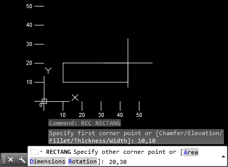
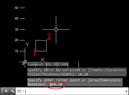
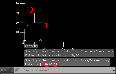
- You can enter coordinates using the last used point to start a new coordinate system.
The entered coordinates must start with "@".
You enter "@10,10" which will make a rectangle with dimensions of 10 sides. Because the previous point was with coordinates "10,10".
- Option where "dynamic input" ≠ is on.
Enter a number in the left field. Press the t button to move to the next field, enter a number in it. Confirm the entered values with e.
These are the coordinates of the opposite corner of the rectangle. Negative values are allowed.
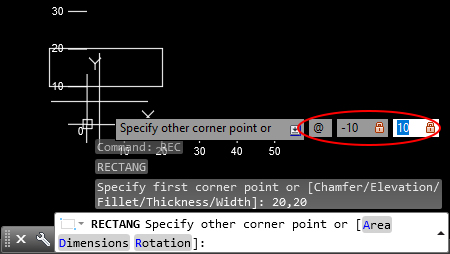
With this command, AutoCAD automatically puts "@" in front of both values. Which means that it accepts the previous point for starting a new coordinate system.


 Български
Terms & Conditions
Subscribe
Report
My comments