Draw a Circle
- Hits: 6889
User Rating: 5 / 5

How to use the circle command and the capabilities it provides.
Principle
- Starting the command.
- Options.
- Choice of starting point.
- Options after selecting a starting point.
- End point selection.
Launch the Circle command
- The first method is to click on the circle icon
 (Depending on the interface, it may look different).
 - The second is to write CI, confirm by pressing the key ß or e - recommended method.
- The third is to repeat the previous command if it was a "circle" by pressing the key ß or e.
Options
As soon as you run the circle command, the following options are displayed: 3P, 2P, Ttr (tan tan radius).

3P
This option allows you to create a circle by defining three points. AutoCAD will create a circle that passes through these three points. Activation is done by typing 3P and after this e. Then you need to select the three points.
There are three points in the example below. To be able to select exactly these points, follow the instructions: After running the command to select the first point, hold q and  . This will open a menu from which you select "Node". Repeat the same procedure for the other two points.
2P
This option allows you to create a circle defined by two points. The circle will always pass through the first selected point. The second point determines the diameter of the circle, as well as the direction in which it should be created. Activation is done by typing 2P and after this e. Then you have to select the two points.
In the example, I select the first point with a mouse click  . For the second point I choose the angle (~ 21 °) and enter "30", which makes the diameter of the circle 30 units. You can also enter a value for the angle by going from field to field via t.
Ttr (tan tan radius)
This option allows you to create a circle that is tangential to two objects (line, circle, etc.) and a certain radius. Activation is done by pressing the key T and after this e. Then you have to select both objects with the left mouse button , to which the circle will be tangential and enter a value for radius. Confirm the entered value with e. It matters where you click because it determines where the circle will be created.
Choice of starting point
- You can select a starting point with the left mouse button .
- Option where "dynamic input" ≠ is disabled.
Enter two numbers separated by a comma "10.10". These are the horizontal coordinates "X" and the vertical "Y". Confirm the entered values with e.

- Option where "dynamic input" ≠ is enabled.
Enter a number for the horizontal coordinate "X". With the button t go to the next field. Enter a number for the vertical coordinate "Y". Confirm the entered values with e.

- Option where "Attach to object" £ is enabled.
A green symbol appears when approaching an attachment point. If you left-click, the beginning of the circle will be where the green marker appeared. Although the cursor is not on the point.

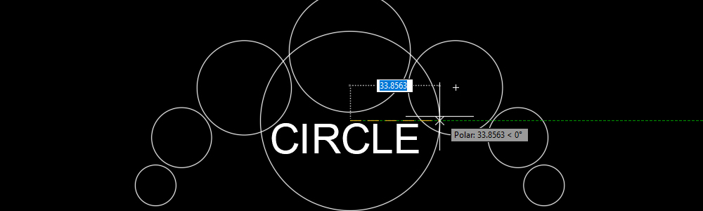
- If you hover over the green symbol, it is marked with a small green plus. You can then move the cursor until a dotted line is displayed. And enter a value such as "20". This will make the beginning of the circle 20 of the specified point in the direction of the dotted line and the cursor. Confirm the entered values with e.

Options after selecting a starting point
After selecting a starting point, AutoCAD will offer you only one option: Diameter

Diameter
This option allows you to set the diameter of the circle.
You start the option with D and after this ß or e, enter a value for the diameter and confirm with e.
End point selection
- If you have not used any of the options, the endpoint determines the radius of the circle.
After selecting the starting point (center of the circle), enter a value for the radius and confirm with e.

 Български
Terms & Conditions
Subscribe
Report
My comments